
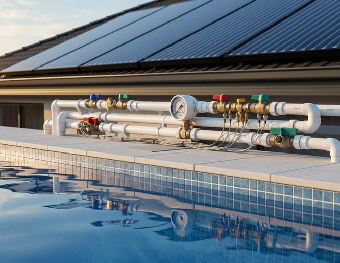
A pool solar heating plumbing diagram maps the complete flow path from your pool through solar collectors and back, showing valve placement, pipe routing, sensor locations, and integration points with your existing filtration system. Understanding this visual guide is essential whether you’re installing a new solar heating system, verifying a contractor’s work, or troubleshooting temperature issues in an existing setup.
The diagram serves as your blueprint for harnessing free solar energy to extend your swimming season by weeks or even months. Unlike complex mechanical systems, solar pool heating relies on elegantly simple physics. Your existing pool pump circulates water through roof-mounted or ground-based solar collectors, where the sun warms it before returning to your pool. The challenge isn’t in how solar pool heating works but in ensuring proper plumbing configuration to maximize heat gain while maintaining adequate flow rates.
Most homeowners find the plumbing aspect intimidating at first glance. You’ll see symbols for check valves, diverter valves, pressure gauges, and automatic controllers. Each component plays a specific role in system efficiency and longevity. A well-designed diagram reveals where to place isolation valves for seasonal maintenance, how to route pipes to minimize heat loss, and where sensors need positioning for automatic temperature control.
This guide breaks down every element you’ll encounter in a solar pool heating plumbing diagram. You’ll learn to interpret standard symbols, understand why certain configurations work better than others, and gain the confidence to either tackle installation yourself or communicate effectively with professionals about your specific setup requirements.
Understanding the Basic Components in Your Plumbing Diagram
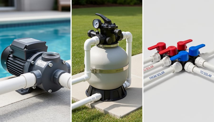
Every pool solar heating plumbing diagram uses a standard set of components that work together to circulate water through your solar collectors and back to the pool. Learning to identify these elements on paper translates directly into understanding how your system operates and where potential issues might arise.
- Solar Collectors
- The panels or tubes mounted on your roof or ground that absorb sunlight to heat pool water flowing through them. Their position in the diagram determines flow patterns and connection points for the entire system.
- Pool Pump
- The heart of water circulation, creating the pressure needed to push water up to collectors and back. Diagram placement shows whether your pump serves dual duty with filtration or operates independently for heating.
- Three-Way Diverter Valve
- Controls whether water flows through the solar collectors or bypasses them directly back to the pool. Its location determines how easily you can switch between heating and non-heating modes.
- Check Valve
- Prevents reverse water flow when the pump stops, protecting collectors from draining or back-pressure damage. Proper placement ensures collectors remain primed and ready for the next heating cycle.
- Temperature Sensor
- Measures pool and collector temperatures to trigger automated valve operation in systems with controllers. Its diagram position indicates optimal placement for accurate readings that maximize heating efficiency.
The filter typically appears before the diverter valve in most diagrams, ensuring clean water reaches your collectors. This positioning matters because debris or calcium buildup in collectors reduces heat transfer and can damage the panels over time. You’ll notice the filter sits between the pump and the point where water diverts toward the collectors.
Connection points and pipe runs shown in diagrams aren’t arbitrary. The route from pump to collectors affects flow rate, which directly impacts heating performance. Shorter runs with fewer bends maintain stronger water pressure, allowing collectors to work at peak efficiency. When collectors sit on a roof, diagrams account for the elevation change, sometimes showing booster pumps or larger pipe diameters to compensate for gravity working against water flow.
Most residential diagrams also include isolation valves at key points, letting you service individual components without draining the entire system. These appear as small symbols along pipe runs and prove invaluable during maintenance or winter shutdown. Understanding where each valve sits helps you control specific sections of your system independently.
How Water Flows Through Your Solar Heating System
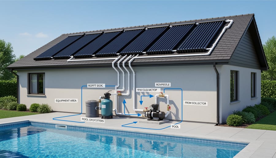
Understanding water flow is fundamental to reading any pool solar heating plumbing diagram. The circulation path follows a logical sequence that maximizes heat transfer while protecting your equipment.
Your pool pump initiates the cycle by pulling water from the main drain and skimmers. This water passes through the filter first, removing debris that could clog the solar collectors. Clean water then reaches the first critical junction: the diverter valve.
When solar heating is active, the diverter valve redirects water upward through supply pipes to the solar collectors. This is where diagrams show elevation changes that affect system pressure. Water climbing to roof-mounted panels works against gravity, which is why proper pump sizing matters. The diagram’s vertical lines indicate this lift requirement.
Inside the collectors, water spreads across hundreds of tubes where sunlight warms it by 10 to 15 degrees on sunny days. The heated water naturally wants to rise, creating helpful convection that reduces the pump’s workload. Most systems achieve a flow rate of 30 to 50 gallons per minute through the collectors, striking a balance between heating efficiency and circulation speed.
After absorbing solar energy, the warmed water exits the collectors and travels down return pipes. A check valve prevents backward flow when the pump stops, protecting against overnight heat loss and potential collector damage from water draining back.
The return line rejoins your main plumbing at a second junction point, where heated water blends with any water that bypassed the collectors through the diverter valve. This mixed water completes the loop by flowing back into your pool.
Proper flow direction appears on diagrams as arrows showing the intended path. Reversing connections creates air locks, reduces heating efficiency by 40 percent or more, and can damage collectors through excessive pressure. The diagram ensures every component handles water moving in its designed direction, extending system life while maintaining consistent heating performance.
Reading Standard Plumbing Diagram Symbols and Notations
When you open a solar pool heating plumbing diagram for the first time, the array of symbols and notations might feel overwhelming. Learning to read these standardized markings transforms a confusing sketch into a clear installation roadmap.
Most diagrams use universal plumbing symbols that cross manufacturer boundaries. Pipes appear as simple lines, with arrows indicating water flow direction. Solid lines typically represent hot water or heated return lines, while dashed lines often show cold water supply routes. The arrow direction is critical because installing components backward can prevent your system from heating effectively.
Valves appear as various geometric shapes positioned along pipe lines. A triangle or bowtie shape usually indicates a check valve that prevents backflow. Three-way diverter valves, which control whether water flows to the collectors or bypasses them, often appear as a Y-shaped junction with a small circle at the intersection point. Ball valves for manual shutoff show as a circle with a line through it, similar to a traditional valve handle position.
Connection points where pipes join are marked with dots or small circles. T-connections appear as perpendicular line intersections, while unions (removable connections) might be shown as two small parallel lines crossing the pipe. Pay attention to these because they indicate where you’ll need specific fittings during installation.
| Symbol | Represents | Function in Solar System |
|---|---|---|
| → (Arrow on line) | Flow direction | Shows which way water travels through pipes |
| ◁ or ▷ (Triangle) | Check valve | Prevents reverse flow when pump stops |
| Y with circle | Three-way valve | Diverts water to collectors or bypass |
| ⊕ (Circle with line) | Ball valve | Manual isolation for maintenance |
| 1½” or 2″ notation | Pipe diameter | Specifies required pipe size for adequate flow |
Measurement specifications appear as numbers adjacent to pipe lines, typically indicating diameter in inches. A “2” means you need two-inch PVC pipe for that section. These measurements ensure proper flow rates and prevent system inefficiency from undersized piping.
Temperature sensor locations are often marked with a small “T” or thermometer symbol. These placements matter for automated systems that need to read water temperature accurately before and after the collectors.
Three Common Plumbing Configurations Explained
Above-Ground Pool Installation Layout
Above-ground pools present the simplest solar heating setup because gravity works in your favor. Your pump typically sits at ground level, just a few feet from the pool wall, which means shorter pipe runs and fewer elevation challenges than in-ground systems face.
The diagram for above-ground installations shows collectors mounted on a nearby fence, shed roof, or ground rack, usually at the same height or slightly below the pool’s waterline. This positioning eliminates the need for powerful pumps to push water uphill. Most systems use the pool’s existing filter pump, which already has the capacity to circulate water through flat or gently-sloped collectors.
Your plumbing diagram will show a direct route from the pump outlet to the collectors, then back to the pool through a simple return line. The key difference from in-ground setups is the minimal use of check valves, since water naturally wants to flow back to the pool rather than drain backward through collectors.
Valve placement stays straightforward: a three-way diverter valve after the filter lets you bypass the collectors when heating isn’t needed. Many above-ground diagrams skip automated controls entirely, using manual valves that you adjust seasonally rather than daily. This simplicity cuts both installation time and costs while maintaining excellent heating performance for smaller pool volumes.
In-Ground Pool with Roof-Mounted Collectors
In-ground pools with roof-mounted collectors represent the most prevalent residential solar heating configuration, and the plumbing diagram for this setup addresses the unique challenge of moving water vertically between your pool and rooftop panels.
The key distinction in this diagram is the extended plumbing run from ground level to your roof. Water leaves your pool pump, passes through the filter, then travels up through dedicated solar supply lines to the collectors mounted on your roof. After absorbing heat, the water returns through separate piping back to your pool return jets. This elevation change typically ranges from 10 to 25 feet, depending on your home’s height.
Proper valve placement becomes critical in this configuration. Your diagram will show a three-way diverter valve positioned immediately after the filter and before the vertical run begins. This valve controls whether water diverts up to the solar collectors or bypasses them entirely when heating is not needed. The diagram also indicates a check valve on the return line near the roof, preventing water from draining back through the collectors when the pump shuts off.
Return line integration requires careful attention to existing pool plumbing. Most diagrams show the solar return connecting to your pool’s main return line rather than creating a separate return jet, simplifying installation while maintaining proper circulation. The diagram should specify union connections at ground level for easy seasonal disconnection in freeze-prone climates.
Ground-Mounted Collector Systems
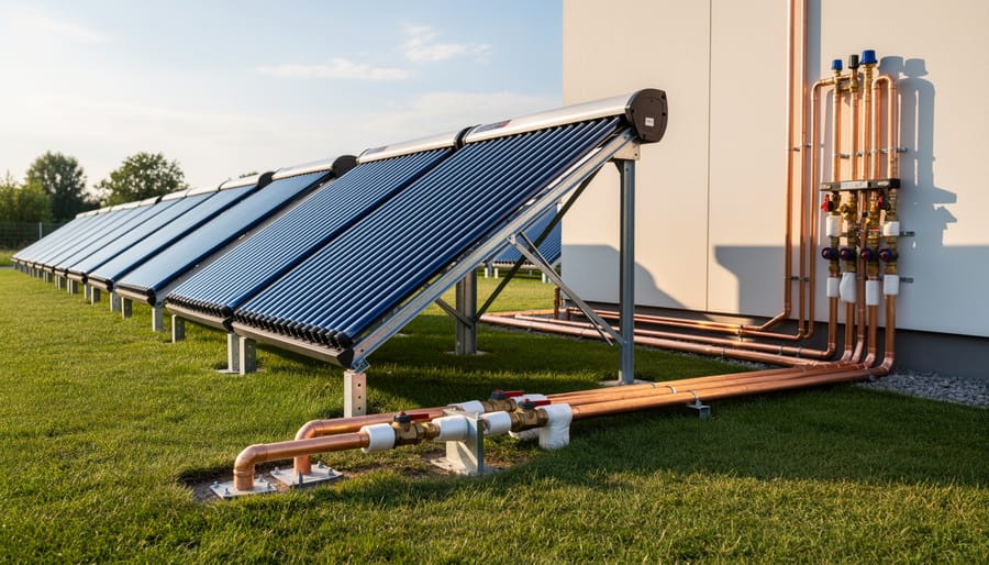
When roof installation isn’t feasible, ground-mounted collectors offer an effective alternative that simplifies your plumbing layout considerably. This configuration works well for properties with adequate yard space and clear sun exposure, eliminating the complexity of vertical pipe runs and roof penetrations.
The primary advantage shows up in your plumbing diagram: shorter pipe distances and minimal elevation changes reduce pump strain and heat loss. Position collectors on a slight incline or level ground within 30 feet of your pool equipment, keeping pipe runs as short as practical. Most diagrams for ground systems show collectors mounted on simple rack systems 12-24 inches above ground level for drainage and air circulation.
Your plumbing diagram will indicate modified valve placement since you’re not fighting gravity. The three-way diverter valve typically sits near the filter output, directing water horizontally rather than upward. Check valves become less critical here but still prevent backflow during shutdowns. Note that ground systems may require larger pipe diameters (2-inch versus 1.5-inch) if your layout involves multiple turns or longer distances.
Plan for proper drainage at the lowest point of your collectors, your diagram should mark drain valve locations for winterization in cold climates. This setup delivers comparable efficiency to roof systems while offering easier access for maintenance.
Critical Valve Placement and Control Integration
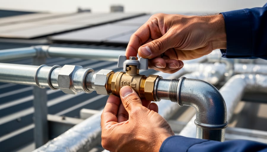
Understanding valve placement transforms a confusing plumbing diagram into a logical roadmap. Each valve in your solar pool heating system serves a specific purpose, and positioning them correctly prevents inefficiency, equipment damage, and frustrating troubleshooting sessions down the line.
The three-way diverter valve sits at the heart of your system, typically installed after your pool filter and before the line splits toward the solar collectors. This valve controls whether water flows through the collectors for heating or bypasses them entirely when heating isn’t needed. On plumbing diagrams, you’ll see this represented as a Y-shaped symbol with three ports labeled “pool,” “solar,” and “return.” Position this valve where you have easy access for manual adjustment or automated control installation.
Check valves prevent backflow and protect your collectors from draining when the pump shuts off. Install one in the return line from the collectors, positioned before it rejoins the main return to your pool. Diagrams show check valves as circles with arrows indicating flow direction. Without this valve, water can siphon back through your collectors overnight, creating air locks and reducing heating efficiency by up to forty percent.
Isolation valves, shown as simple rectangular symbols on diagrams, go on both sides of your solar loop. These let you shut off and service the solar portion without affecting normal pool circulation. Place one before the diverter valve sends water to the collectors and another on the return line after the check valve.
Critical valve placement rules that prevent common installation mistakes:
- Never install the diverter valve before the filter, which forces debris through your collectors
- Position check valves with the arrow pointing away from collectors toward the pool
- Mount diverter valves at least twelve inches from any wall for actuator clearance
- Keep all valves accessible without requiring ladder work for seasonal adjustments
- Install isolation valves far enough apart to accommodate union fittings for easy removal
For automated control integration, your diagram will show a sensor probe location on the collector outlet pipe and a control box connection to the diverter valve actuator. The actuator, typically a small electric motor that rotates the valve, mounts directly onto the three-way valve body. Modern controllers use temperature differential logic: when collectors are warmer than the pool by a set amount (usually eight to twelve degrees), the controller signals the actuator to divert water through the heating loop.
Manual systems skip the actuator and use a simple handle on the three-way valve, which you rotate based on weather conditions and pool temperature. While this requires more attention, it eliminates electrical components and reduces initial costs. Diagrams for manual setups show the same valve positions but without the control box and sensor wire notations. Either approach works reliably when valves are positioned according to the fundamental rules of flow, access, and system protection your plumbing diagram illustrates.
Sizing Your Pipes and Planning Connections
Your plumbing diagram typically includes pipe diameter specifications at key points throughout the system. Most residential solar pool heating installations use 1.5-inch or 2-inch PVC pipe as the main supply and return lines, matching your existing pool plumbing size. The diagram should show these dimensions labeled at each section, helping you maintain consistent flow rates and avoid bottlenecks that reduce efficiency.
Undersized pipes create excessive friction and strain your pump, while oversized pipes waste materials and increase costs without performance benefits. A standard rule: your solar heating pipes should match or slightly exceed your existing pool circulation pipe diameter. For pools under 20,000 gallons with collectors covering 300-400 square feet, 1.5-inch pipe usually suffices. Larger systems require 2-inch piping to handle the increased water volume cycling through elevated collectors.
Connection points demand careful planning. Your diagram shows where the supply line taps into your existing system (typically after the filter but before any heater) and where the return line reconnects (usually at the pool return plumbing). These junction locations matter because improper placement affects hydraulic balance and can interfere with other equipment like chlorinators or existing heaters.
Flow rate indicators on professional diagrams help you calculate collector heat output and verify your pump can handle the additional load. Look for specifications like “minimum 30 GPM” or “flow range 40-60 GPM” near the collector symbols. Compare these requirements against your pump’s rated capacity to confirm compatibility.
Pay attention to elevation changes marked on the diagram. Vertical runs to roof-mounted collectors need adequate pipe diameter to overcome gravity and maintain proper flow when the system shuts off, preventing backflow issues that damage collectors.
Using Your Diagram for a Professional Installation
A well-drawn plumbing diagram becomes your roadmap from planning to final connection. Start by printing or displaying your diagram at full size where you can reference it constantly throughout the installation. Compare it against your existing pool equipment and the space where collectors will mount to confirm all distances and measurements match reality before ordering materials.
Gather your supplies based on the diagram’s specifications. You’ll need PVC pipe in the diameters shown, the correct valve types (three-way diverters, check valves, isolation valves), pipe cement and primer, supports for mounting collectors, and all fittings indicated in your layout. Quality materials make a difference in system longevity, especially for components exposed to sun and weather.
Follow this workflow to translate your diagram into a functioning system:
- Install and secure your solar collectors in their designated positions, verifying proper angle and orientation before permanently mounting them.
- Measure and cut pipe runs according to the diagram’s routing, leaving extra length initially so you can trim for perfect fits during assembly.
- Install valves in their exact specified locations, ensuring three-way diverters point the correct direction to allow both solar and bypass modes.
- Connect supply lines from your pool pump’s outlet through the filter to the collector inlet, following the diagram’s elevation path carefully.
- Complete return lines from collector outlets back to the pool, installing check valves at points indicated to prevent reverse flow.
- Mount your temperature sensor exactly where the diagram specifies for accurate automated control.
- Test all connections with a pressure check before filling the system, confirming no leaks exist.
Proper installation means your system meets NEC solar code requirements and local building standards. Double-check that pipe slopes match the diagram to prevent air pockets that reduce efficiency. Secure all horizontal runs every four feet and support vertical sections to prevent sagging over time.
The eco-friendly benefit of solar pool heating only delivers when installation follows the diagram precisely. A correctly installed system operates with minimal pump energy while eliminating gas or electric heating costs completely. Take photos at each major connection point that match your diagram. These become invaluable references for future maintenance or winterization procedures.
Troubleshooting with Your Plumbing Diagram
Your plumbing diagram becomes an invaluable diagnostic tool when system performance drops. Start by tracing the water flow path on your diagram while listening to your running pump. Air locks typically occur at high points in the plumbing, especially where collector return lines enter the main system. If you hear gurgling or notice reduced flow, check these elevated connection points shown in your diagram. Bleeding air through the system’s highest valve often resolves the issue.
When collectors aren’t heating adequately, verify that your three-way diverter valve matches the position indicated for solar mode on your diagram. A partially closed or stuck valve restricts flow to collectors, preventing proper heating. Compare the valve’s actual position against the diagram’s flow arrows to confirm water is routing correctly through the solar loop rather than bypassing it entirely.
Low flow problems usually stem from clogged filters or closed isolation valves. Reference your diagram to locate each valve in the solar circuit and verify they’re fully open. Check that your pump’s output matches the flow rate specifications noted on the diagram. Undersized pumps cannot push water through the additional resistance of roof-mounted collectors.
Leaks are easiest to diagnose by working backwards from the wet area using your diagram’s pipe routing. This systematic approach, combined with proper service quality assurance practices, helps identify whether issues originate in connections, valve bodies, or collector headers themselves.
Understanding your solar pool heating plumbing diagram transforms installation from intimidating guesswork into a straightforward, manageable process. Whether you’re planning a DIY project or working with a contractor, that diagram serves as your roadmap to a system that actually works as intended. The time you invest now in comprehending component placement, flow direction, and valve positioning pays dividends for years through reliable performance and minimal maintenance headaches.
Proper installation following a clear diagram directly impacts your system’s sustainability credentials. When water flows efficiently through correctly sized pipes and properly positioned collectors, you maximize heat gain while minimizing pump runtime. That translates to lower energy consumption and a smaller environmental footprint. It’s also why systems sit unused when installation shortcuts create frustrating performance issues that erode confidence in solar heating.
Keep your plumbing diagram accessible after installation. It becomes invaluable when troubleshooting, planning system expansions, or explaining your setup to future service providers. The confidence that comes from understanding your system empowers you to maintain it properly and enjoy the cost savings and eco-friendly benefits that motivated your solar heating investment in the first place.
Ready to start planning your installation? Take that next step toward sustainable pool heating that works reliably season after season.